Tampilkan postingan dengan label elektronika. Tampilkan semua postingan

Jumat, 30 Desember 2011

speaker Aktif Polytron Dengung

seorang teman di fesbuk dapat servisan speaker aktif merk politron memakai power suplay switching ( acemathic )dengan kerusakan dengung..................
solusinya elko 4700uf50v X 2 pada power suplay regulator gemblung jadi setelah diganti alhamdulillah langsung mak nyes bayaran lagi.....

DATA LETAK TITIK PROTEKSI TV SHARPN

moga bermanfaat bwt tmn2x tekhnisi yang sdg mengalami kesulitan dalam menghadapi kendala sistem proteksi pd tv sharp
PROTEKSI SHARP
Chasis UA-1, Menggunakan IC IX3368CEN1-5 Atau IX3410CEN1-5
Masukan Proteksi Detektor Yang Dideteksi Tegangan Normal Menonaktifkan Proteksi
Pin No.8 IC801 (3,3 V)
Menonaktifkan Proteksi utama,
Lepaskan Jumper J223 D609 Tegangan 8V Anoda D609 = 3.3 Volt Lepaskan D609
D606 ABL / X-ray Anoda D606 = 3.3 Volt Lepaskan D606
D614, Q603 Heater / X-ray Anoda D614 = 3.3 Volt
Collector Q603 = 3.3 Volt Lepaskan D614
Lepaskan Q603
D752 Tegangan 5V Anoda D752 = 3.3 Volt Lepaskan D752
D504 Tegangan 16V (Sound Amp) Anoda D504 = 3.3 Volt Lepaskan D504
D502 Tegangan 45V (Vertikal) Anoda D502 = 3.3 Volt Lepaskan D502
D503 Vertikal Output Anoda D503 = 3.3 Volt Lepaskan D503
D613 Tegangan 180V Anoda D613 = 3.3 Volt Lepaskan D613
Chasis UA-1 (Lubang), Menggunakan IC IX3368CEN7
Masukan Proteksi Detektor Yang Dideteksi Tegangan Normal Menonaktifkan Proteksi
Pin No.8 IC801 (3,4 V)
Menonaktifkan Proteksi utama,
Lepaskan Jumper J208 dan D203 D203 Tegangan 33V (Tuner) Anoda D203 = 3.4 Volt Lepaskan D203
D607 Tegangan 190V Anoda D607 = 3.4 Volt Lepaskan D607
D604, Q603 Heater / X-ray Anoda D604 = 3.4 Volt
Collector Q603 = 3.4 Volt Lepaskan D604
Lepaskan Q603
D601 ABL / X-ray Anoda D601 = 3.4 Volt Lepaskan D601
Q501 Tegangan Supply Vertikal Collector Q501 = 3.4 Volt Lepaskan D501
Menggunakan IC IX 2938CE, TB1226
Masukan Proteksi Detektor Yang Dideteksi Tegangan Normal Menonaktifkan Proteksi
Pin No.30 IC1001 (5,1 V) D616 Tegangan 9V Anoda D616 = 5.1 Volt Lepaskan D616
D607 Tegangan 180V Anoda D607 = 5.1 Volt Lepaskan D607
Q607 Heater / X-ray Collector Q607 = 5.1 Volt Lepaskan Q607
D606 ABL / X-ray Anoda D606 = 5.1 Volt Lepaskan D606
D611 Tegangan 5V Anoda D611 = 5.1 Volt Lepaskan D611
D201 Tegangan 9V Anoda D201 = 5.1 Volt Lepaskan D201
Menggunakan IC IX 2694, M52340
Masukan Proteksi Detektor Yang Dideteksi Tegangan Normal Menonaktifkan Proteksi
Pin No.38 IC1001 (0 V) D606 Heater / X-ray Anoda D606 = 0 Volt Lepaskan D606
D616 ABL / X-ray Anoda D616 = 0 Volt Lepaskan D616
Q603 ABL / X-ray Collector Q603 = 0 Volt Lepaskan Q603
D610 Heater / X-ray Anoda D610 = 0 Volt Lepaskan D610
Chasis G2 Menggunakan IC IX 3031CE, TB1226
Masukan Proteksi Detektor Yang Dideteksi Tegangan Normal Menonaktifkan Proteksi
Pin No.30 IC1001 (3,3 V) D618 Tegangan 9V Anoda D618 = 3,3 Volt Lepaskan D618
D607 Heater / X-ray Anoda D607 = 3,3 Volt Lepaskan D607
Q607 Heater / X-ray Collector Q607 = 3,3 Volt Lepaskan Q607
D606 ABL / X-ray Anoda D606 = 3,3 Volt Lepaskan D606
D611 Tegangan 5V Anoda D611 = 3,3 Volt Lepaskan D611
GA-4M Chasis, Menggunakan IC IXB226WJ, M61260
Masukan Proteksi Detektor Yang Dideteksi Tegangan Normal Menonaktifkan Proteksi
Pin No.7 IC1001 (4.5 V) D605 Tegangan 185V Anoda D605 = 4,5 Volt Lepaskan D605
D608 ABL / X-ray Katoda D607 = 4,5 Volt Lepaskan D608
Q603 Heater Collector Q603 = 4,5 Volt Lepaskan Q603
D203 Tegangan 33V (Tuner) Anoda D203 = 4,5 Volt Lepaskan D203
D1091 Tegangan 9V Anoda D606 = 4,5 Volt Lepaskan D1091
Pin No.6 IC1001 (3.4 V) D1010 Tegangan 15V Pin No.6 IC1001 = 3.4 Volt Lepaskan D1010
Chasis GA-6, Menggunakan IC IXB725WJ, Chasis GA-7 Menggunakan IC IXB855WJZZ
Masukan Proteksi Detektor Yang Dideteksi Tegangan Normal Menonaktifkan Proteksi
Pin No.63 IC801 (4.1 V) D1005 Tegangan 9V Anoda D1005 = 4,1 Volt Lepaskan D1005
D608 ABL / X-ray Katoda D608 = 4,1 Volt Lepaskan D608
Q603 Heater Collector Q603 = 4,1 Volt Lepaskan Q603
D805, D203 Tegangan 33V (Tuner) Anoda D805 & D203 = 4,1 Volt Lepaskan D203
D204 Tegangan 5V (Tuner) Anoda D204 = 4,1 Volt Lepaskan D204
Pin No.7 IC801 (3.9 V) D1002 Power supply (AC-Detect) Pin No.7 IC801 = 3.9 Volt Lepaskan D1002
Pin No.8 IC801 (0.6 V) R523 Vertical Pin No.8 IC801 = 0.6 Volt Lepaskan R523
Menggunakan IC IXC080WJN5Q
Masukan Proteksi Detektor Yang Dideteksi Tegangan Normal Menonaktifkan Proteksi
Pin No.63 IC801 (4.1 V)
Menonaktifkan Proteksi utama,
Lepaskan Jumper J497 D1108 Tegangan 5V Anoda D1008 = 4,1 Volt Lepaskan D1108
D605 Tegangan 185V Katoda D605 = 4,1 Volt Lepaskan D605
D608, D607 ABL / X-ray Katoda D608 = 4,1 Volt Lepaskan D608
Q603, D604 Heater / X-ray Collector Q603 = 4,1 Volt Lepaskan Q603
D203 Tegangan 33V (Tuner) Anoda D203 = 4,1 Volt Lepaskan D203
D1105 Tegangan 5V Anoda D1105 = 4,1 Volt Lepaskan D1105
Pin No.64 IC801 (3.9 V) D1002 Power supply (AC-Detect) Pin No.64 IC801 = 3.9 Volt Lepaskan D1002
Pin No.65 IC801 (0.6 V) R523 Vertical Pin No.65 IC801 = 0.6 Volt Lepaskan R523
Menggunakan IC IXC688WJ / IC IXC844WJ
Masukan Proteksi Detektor Yang Dideteksi Tegangan Normal Menonaktifkan Proteksi
Pin No.81 IC801 (4.1 V) D1108 Tegangan 5V Anoda D1008 = 4,1 Volt Lepaskan D1108
D605 Tegangan 185V Katoda D605 = 4,1 Volt Lepaskan D605
D608, D607 ABL / X-ray Katoda D608 = 4,1 Volt Lepaskan D608
Q603, D604 Heater / X-ray Collector Q603 = 4,1 Volt Lepaskan Q603
D203 Tegangan 33V (Tuner) Anoda D203 = 4,1 Volt Lepaskan D203
D1105 Tegangan 5V Anoda D1105 = 4,1 Volt Lepaskan D1105
Pin No.82 IC801 (3.9 V) D1002 Power supply (AC-Detect) Pin No.82 IC801 = 3.9 Volt Lepaskan D1002
Pin No.83 IC801 (0.6 V) R523 Vertical Pin No.83 IC801 = 0.6 Volt Lepaskan R523
by pyondsound

Rabu, 28 Desember 2011

Bagaimana Cara Menentukan Nilai Resistor Pada Lampu LED

How to choose a resistor to turn on the LED? Why LEDs need resistors? That's because the LED does not have a current regulator, the LED will burn out if no resistor.

The amount of flow determines how bright an LED. Greater flow of the lighter flame of an LED. Current in the LED should be approximately 10-20 mA. When a current passes through a LED, the LED voltage drop of about 1.85 V or depending on the type of LED that is in use


To determine the resistor on the led first consider the graph above (right graph ). Choose the desired LED light and use this chart to determine the required flow. For example, if the desired luminous intensity (high / dark light an LED) for 1, can be seen that the currents are in need of 20 mA.

This shall mean the current 20 mA to pass through the LED, to get the brightness of LED = 1. Now, we can calculate the voltage drop across the LED based on a known flow. Look at the graph on the left at 20 mA. Now you know that the fall in voltage of 1.85 V. Know that the voltage drop across the LED is not only a function of current, but also the color of the LED and the temperature (because of chemical differences in the LED).

Color Potential Difference (LED voltage)

Infrared : 1.6 V
Red : 1.8 V - 2.1 V
Orange : 2.2 V
Yellow : 2.4 V
Green : 2.6 V
Blue : 3.0 V - 3.5 V
White : 3.0 V - 3.5 V
Ultraviolet : 3.5 V

The following example circuit LED (Menentukan Nilai Resistor Pada LED) series / parallel based on Ohm's law, V = IR to refer to the list above the LED voltage


Resistor values = (voltage source - LED voltage) / LED current

Red LED resistor values (12 V- 1.8V) /0.02 A = 510 ohms
Blue LED resistor values (12V - 3V) / 0.02 A = 450 ohms

Resistor values = (voltage source - the total LED voltage) / LED current

Resistor values = (12V - 9.6 V) / 0.02 A = 120 ohms

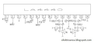
Rangkaian Amplifier pake IC LA 4440

This is the circuit of amplifier using IC LA4440. The amplifier circuit uses very less components but a very high quality with respect to its cost and ideal for beginners.

IC LA 4440 is wired as a bridge amplifier to deliver a 19 W Rms on a 4 Ohm speaker atau 6 W rms jika di fungsikan stereo. The IC has built in thermal over voltage and short circuit protection.The IC also incorporates a audio muting function.

Rangkaian 19 Watt Bridge Amplifier LA4440Rangkaian 19 Watt Bridge Amplifier LA4440
Rangkaian 6 Watt Stereo Amplifier LA4440Rangkaian 6 Watt Stereo Amplifier LA4440

Note:

Use a 12 VDC / 3 A power supply, IC LA4440 can with stand up to 18 volts, but I prefer it should not be nothing more than 16V.
Do not forget to fit a proper heat sink with IC.
Use a 4 Ohm speaker

IC LA4440 Features

Built-in 2 channels enabling use in stereo and bridgeamplifier applications. (Stereo 6 Watt Bridge : 19W)
Minimun number of external parts required.
Small pop noise at the time of power supply ON/OFF and
good starting balance.
Good ripple rejection : 46dB (typ.)
Good channel separation.
Small residual noise (Rg=0).
Low distortion over a wide range from low frequencies to high frequencies.
Easy to design radiator fin.
Built-in audio muting function.
Built-in protectors.
Thermal protector
Overvoltage, surge voltage protector
cPin-to-pin short protector

Quick Data IC LA4440

Maximum supply voltage.............................18 V.
Allowable power dissipation Pd max............15 W.
Operating temperature Topr........................–20 to +75.
Storage temperature Tstg............................–40 to +150.
Voltage gain VG..........................................49.5 to 53.5.
Output power PO....................................... Stereo 06 W, Bridge 19 W.
Input resistance ri ............................. ....... 30kOhm.

Rangkaian Amplifier 5 Watt - Class A

Rangkaian Amplifier yang sangat sederhana.dapat copy dari blog lain,katanya Rangkaian amplifier ini walau sederhana tapi berkualitas.membutuhkan catu daya 24 V dan ouput 3-5 watts.

Parts:

P1_____________47K Log. Potentiometer (Dual-gang for stereo)

R1____________100K 1/4W Resistor
R2_____________12K 1/4W Resistor
R3_____________47K 1/4W Resistor
R4______________8K2 1/4W Resistor
R5______________1K5 1/4W Resistor
R6______________2K7 1/4W Resistor
R7,R9_________100R 1/4W Resistors
R8____________560R 1/2W Resistor
R10_____________1R 1/2W Resistor

C1,C2__________10µF 63V Electrolytic Capacitors
C3_____________47µF 25V Electrolytic Capacitor
C4____________100µF 35V Electrolytic Capacitor
C5____________150nF 63V Polyester Capacitor atau Mylar Capacitor
C6,C7_________220µF 25V Electrolytic Capacitors
C8___________1000µF 25V Electrolytic Capacitor

Q1___________BC560C
Q2,Q3________BD439 atau BD437

SPKR___________One or more speakers wired in series or in parallel
Total resulting impedance: 8 Ohm
Minimum power handling: 5W

Circuit diagram:
3 - 5 Watt Amplifier

Senin, 19 Desember 2011

eh,ade Proteus 7.8 SP2 7.8sp2 2011 + Crack

eh,ade Proteus 7.8 SP2 .ada crackya lagi.download ah .... !!
insya Allah kalau udah banyak duit mau beli program simulator yang asli ....

Proteus 7.8 SP2 7.8sp2 10468 x86 2011 + Crack | 104MB


Proteus Professional - a software package for computer-aided design of electronic circuits. The package is a system of circuit simulationbased on models of electronic components made in PSpice.
Proteus 7.8 SP2 7.8sp2 10468 x86 2011 + Crack


Proteus 7.8 SP2 7.8sp2 10468 x86 2011 + Crack | 104MB


Proteus Professional - a software package for computer-aided design of electronic circuits. The package is a system of circuit simulationbased on models of electronic components made in PSpice.
A distinctive feature of the package Proteus Professional is the possibility of simulating the operation of programmable devices: microcontrollersmicroprocessorsDSP and others. Additionallythe package Proteus Professional is a system design of printed circuit boards. Proteus Professional can simulate the operation of the following microcontrollers: 8051ARM7AVRMotorolaPICBasic Stamp. Component library of reference data.
Starting with version 7.8 there VSM IDE to debug the project with microcontrollers

Changes in version 7.8:
- Use templates PCB c ability to save settings PCB
- Change the default background color in ARES
- Toggle the visibility of layers and colors in ARES
- Improved strip conductors in the ISIS
- Displaying the size of the contact areas in the preview window in ARES
- Added examples for the AVR and 8051
- Help file rewritten in CHM format
If you are installing to specify the key Users of the former USSR_LICENCE.lxkafter installation run the patch LXK Proteus 7.8 SP2 RUS v1.0.0.exe on windows Vista and Seven run as administrator
Year / Date of Release: 2011
Version: 7.8sp2 Build 10468
Developer: Labcenter Electronics
Bit depth: 32bit
Compatibility with Vista: complete
Compatible with Windows 7: complete
Language: English

Download from fileserve.com
http://www.fileserve.com/file/ANtWXzB/Proteus.part1.rar
http://www.fileserve.com/file/7hHU68c/Proteus.part2.rar


Download from filesonic.com
http://www.filesonic.com/file/1173924554/Proteus.part1.rar
http://www.filesonic.com/file/1173885684/Proteus.part2.rar


Download from ul.to
http://ul.to/qxuowx5l/Proteus.part1.rar
http://ul.to/x9zabseu/Proteus.part2.rar


Download from uploadstation.com
http://www.uploadstation.com/file/8XrMfvn/Proteus.part1.rar
http://www.uploadstation.com/file/sXM5V5r/Proteus.part2.rar


Download from wupload.com
http://www.wupload.com/file/13659428/Proteus.part1.rar
http://www.wupload.com/file/13658167/Proteus.part2.rar